A low earth-pit resistance reading does not, by itself, prove that a commercial building will clear an electrical fault safely. You will learn what the pit contains, which tests answer which safety questions, how technicians obtain reliable readings, and how to judge a report against the approved design and named requirements.
Key takeaways
- A low earth resistance reading does not prove protective conductors are continuous.
- Use fall-of-potential testing for an independent earth-electrode resistance result.
- Check test leads, probe spacing, isolation controls and weather conditions before testing.
- Ask for the test method, instrument details, readings, location and technician’s signature.
What an earth pit protects—and what its reading cannot prove
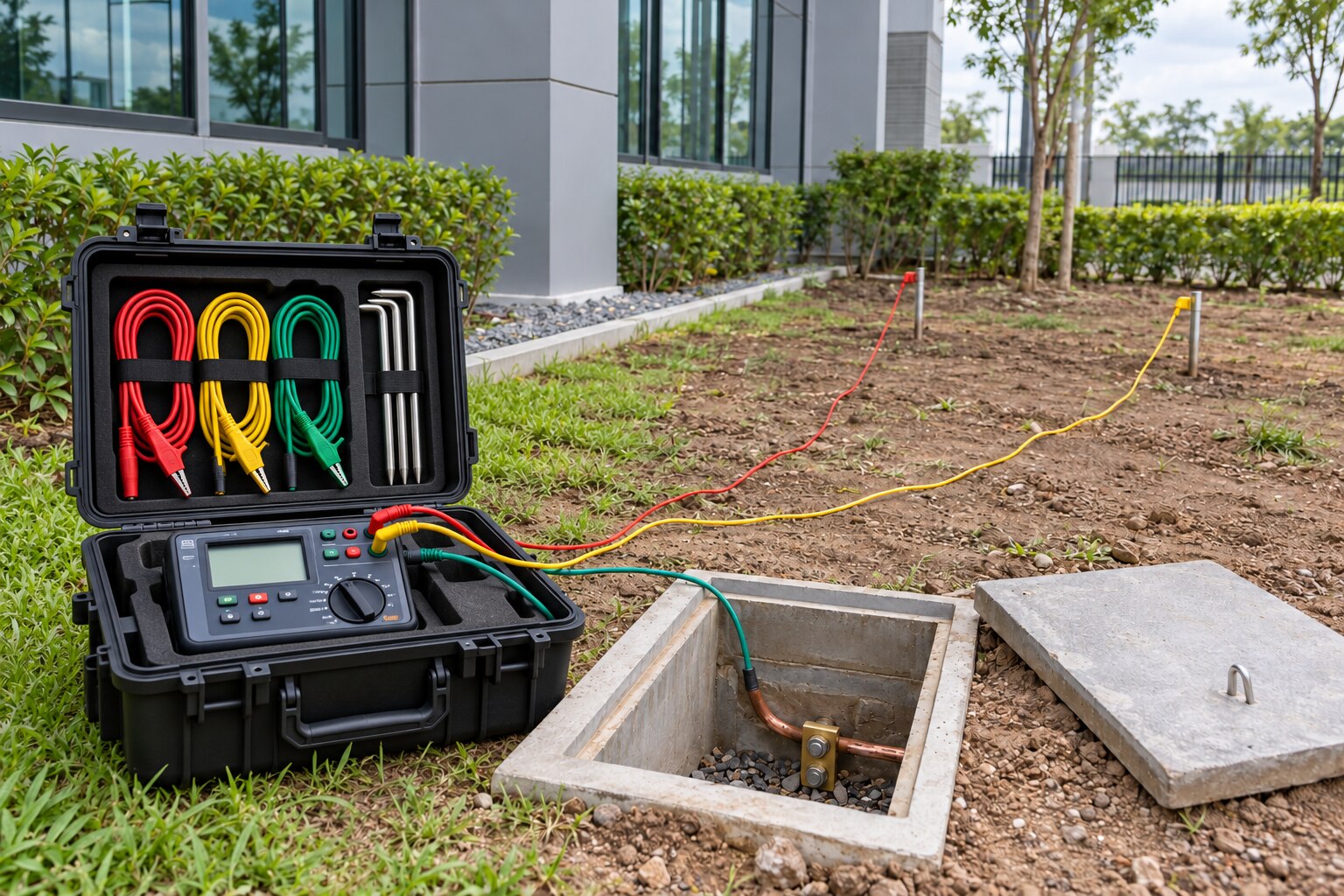
An earth pit provides a connection between the soil and a building’s protective earthing system. Its main parts are:
- Earth electrode: a rod, pipe, plate or other buried conductor that contacts the soil.
- Earth-enhancing material: conductive compound placed around the electrode where the design specifies it.
- Inspection chamber: the accessible enclosure protecting the connection and allowing examination.
- Test link: a separable joint used to isolate the electrode for testing, under controlled conditions.
- Earthing conductor: the conductor joining the electrode to the building’s earthing terminal or network.
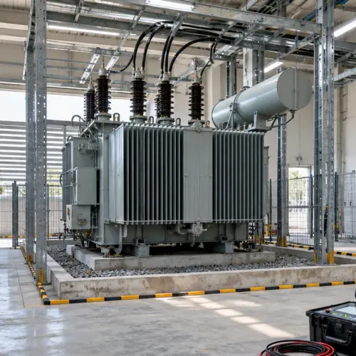
A low-impedance fault-current path helps a fuse, circuit-breaker or residual-current device disconnect supply quickly when a live conductor touches a metal enclosure. Faster disconnection limits touch voltage, reducing shock risk and limiting damage to cables, equipment and switchgear.
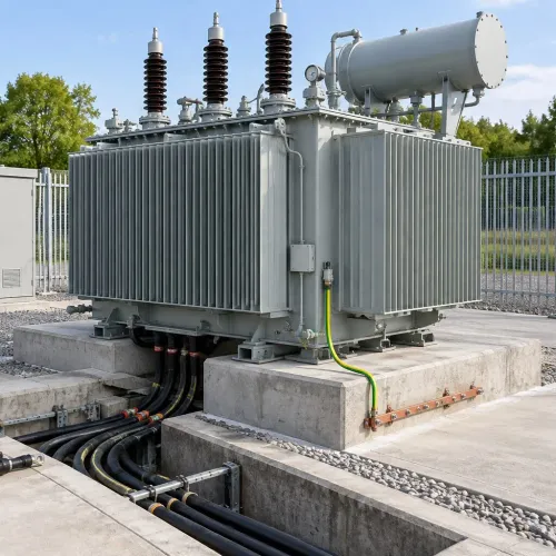
The number displayed at an accessible earth pit does not necessarily represent that electrode alone. Structural steel, water services, cable armour, other pits and lightning-protection conductors can create parallel paths, so the reading may represent an interconnected earthing network.
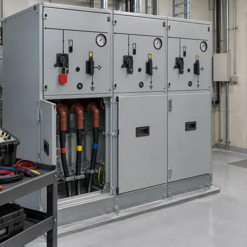
It does not prove correct bonding at sockets, distribution boards, transformers or equipment bodies, nor does it establish that a lightning-protection system’s complete earth-termination and bonding arrangement is sound.
A damaged protective conductor, undersized cable or loose connection can remain dangerous despite a low pit value; earth fault-loop impedance, continuity and automatic-disconnection tests answer those safety questions.
Which electrical test answers the safety question you have
The right test depends on the safety question. A low earth resistance reading does not prove that a damaged protective conductor or loose bond will carry enough fault current to operate a breaker.
| Test | What it answers | Practical meaning |
|---|---|---|
| Earth resistance | Does the electrode or connected earth network connect effectively to soil? | Measures the electrode system; an interconnected building network can affect the result. |
| Earth fault-loop impedance | Will enough fault current flow for the protective device to disconnect within the required time? | Includes the fault path, supply return path and protective conductor. |
| Protective-conductor continuity | Is the protective path unbroken and low resistance? | Checks conductors, bonding straps and connections from equipment back to the earthing system. |
| Insulation resistance | Is unwanted leakage present? | Checks resistance between live conductors and earth, or between conductors. |
For a three-point fall-of-potential test, use a calibrated earth resistance tester, a remote current electrode and a potential electrode. The tester injects current through the current electrode and measures voltage through the potential electrode to calculate earth resistance. Keep both probes sufficiently remote; overlapping voltage gradients create unstable or falsely low results.
A selective or clamp-based test suits a site only when parallel return paths exist through other electrodes, bonding conductors, cable armour or metallic services. A clamp tester cannot validly measure an isolated electrode because it needs that parallel path.
Commissioning verification must also include:
- Protective-conductor continuity
- Insulation resistance and polarity
- Automatic disconnection of supply
- RCD trip-time or trip-current testing, where applicable
- Functional checks of protective and control systems
How technicians obtain a reliable and safe earth-pit result
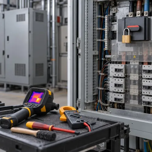
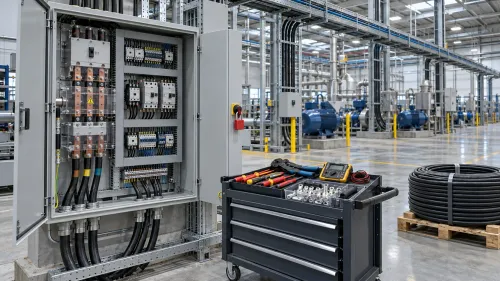
Before connecting a probe, identify buried cables, pipes and other services from drawings, scans and site markings. Obtain the permit, control or isolate hazardous sources, and assess transferred touch potentials before opening any test link or disconnecting a bonding connection.
Inspect the chamber, electrode, earthing conductor and accessible joints for corrosion, looseness, water ingress, mechanical damage and deterioration. Photograph defects and record which connections remain bonded; a clean-looking chamber does not prove a sound buried joint.
- Connect a calibrated earth resistance tester to the electrode under test, a remote current electrode and a remote potential electrode.
- Run the three-point fall-of-potential testing sequence, injecting current through the current electrode and measuring voltage through the potential electrode.
- Increase probe spacing until readings stabilise. Overlapping voltage gradients produce unstable or falsely low results, so a convenient nearby probe is not reliable evidence.
- Treat the familiar 62% potential-probe position as valid only for a single electrode in reasonably uniform soil. Use a probe-position survey or fall-of-potential curve for grids, interconnected pits, structural steel or layered ground.
- Use selective testing or a clamp earth tester only when parallel return paths are present and understood. Do not clamp-test an isolated electrode; parallel electrodes, cable armour, utility neutrals or bonding conductors can distort the result.
After testing, reconnect every opened link or bond, tighten and secure each joint, replace covers, and perform a restoration check. Confirm that protective and lightning-current paths are continuous before the permit is closed.
How to interpret the number, standards and test report
A reading such as 1 ohm is not a universal pass value. Accept the result only against the approved earthing design, system voltage, soil conditions, protective-device coordination, utility or authority requirement, and project electrical specification—not an internet benchmark.
| Comparison basis | Why it changes acceptance | What to verify |
|---|---|---|
| Approved earthing design | Electrode networks and fault-current targets differ | Design drawing and calculated values |
| System and protection | Disconnection depends on fault-loop impedance and device settings | Voltage, breaker or RCD coordination |
| Site conditions and authority | Soil and local rules affect the permitted result | Soil report, utility requirement and project specification |
Require the earth-pit test report to name the exact edition of IS 3043, applicable provisions of the Central Electricity Authority Safety Regulations, 2023, IEC 60364-6 where used, and the project specification.
It must record the date, weather or soil condition, test configuration, bonded electrode connections, instrument make and model, calibration status, current and potential probe distances, readings, and corrective actions.
Wet-season resistance can be materially lower than dry-season resistance. Trend records are useful only when those conditions, the instrument, configuration and probe distances are recorded consistently.
For maintenance, inspect and act on the physical defect:
- Repair loose or corroded joints, damaged conductors and water ingress.
- Do not use salt or extra earth compound to hide a defective connection; salt can accelerate corrosion.
- Assess lightning protection through its complete earth-termination, conductor-routing and equipotential-bonding arrangement, not through a pit number alone.
When commercial buildings need testing and what to ask the contractor
Routine earth testing should follow risk and change, not a calendar alone. Test after a new installation or alteration, an earth fault or lightning event, repeated breaker trips, or corrosion, flooding or physical damage to a pit.
The site inspection and maintenance plan, approved design and authority requirement set routine intervals; an annual pit reading cannot replace a post-fault investigation.
| Event | Required response | Safety question |
|---|---|---|
| New installation or alteration | Verify continuity, insulation, earth resistance, fault-loop impedance, polarity, automatic disconnection and RCD operation where applicable | Will protection operate? |
| Fault, lightning or repeated trips | Inspect conductors, bonds, panels, protective devices, insulation and fault-loop performance | What failed, and will it recur? |
| Pit corrosion, flooding or damage | Inspect and repair the electrode, chamber, test link and joints before retesting | Is the path physically sound? |
Ask the contractor:
- Which pits, structural bonds, lightning systems and other earth paths remain connected?
- Is the objective network resistance or an individual electrode?
- Will the method be three-point fall-of-potential, selective or clamp-based testing? A clamp method is unsuitable for an isolated electrode without parallel return paths.
- How will isolation, permits and transferred touch potentials be controlled?
- What restoration checks confirm every bond is reconnected and secure?
Navyashree Engineers Private Limited can add value by coordinating testing with HT/LT systems, facility maintenance and documented commercial building electrical safety records, provided the scope names each test and its acceptance basis rather than promising only a resistance number.
Frequently asked questions
What does an earth pit protect, and what can its reading not prove?
The earth pit helps carry fault current into the soil and supports protective-system operation. Its resistance reading alone does not prove that every bonding conductor, connection or protective device will operate correctly.
Which electrical test answers the safety question you have?
Use earth-electrode resistance testing to assess the pit-to-soil connection, continuity testing to check protective conductors and bonding, and protective-device tests to confirm disconnection performance.
How do technicians obtain a reliable and safe earth-pit result?
They control isolation and touch-voltage risks, inspect connections, place test probes correctly, use a suitable calibrated instrument and record conditions that could affect the result.
What should an earth-pit test report contain?
Request the pit identification and location, test date, method, instrument and calibration details, probe arrangement, measured resistance, site conditions, observations, deviations and technician’s signature.