
A commercial wiring plan must connect the utility service to every final circuit while keeping power, communications and life-safety systems safe, accessible and testable. By the end, you will know how to map the electrical layers, calculate demand, select cables and containment, separate low-voltage systems, and prepare the records needed for approval and future maintenance.
Key takeaways
- Map utility, distribution, final circuits and low-voltage systems separately.
- Calculate demand, voltage drop and fault current before choosing cable sizes.
- Separate power, data, fire alarm and security pathways with labelled containment.
- Test every circuit, record results and schedule inspections before handover.
Map the electrical layers and calculate demand before selecting cables
Structure the system from the utility connection inward: the service entrance feeds the main distribution board, which supplies sub-distribution boards and then final circuits. Map lighting circuits, socket circuits, dedicated equipment feeders, HVAC loads and low-voltage systems separately so one overloaded category does not hide another.
1. Confirm the governing basis before design: the electrical code edition adopted by the local authority having jurisdiction, local amendments, utility rules, fire-code requirements and inspection authority. The newest NFPA 70 (NEC) edition alone does not guarantee approval.
2. Build an equipment schedule showing each load’s quantity, rated voltage, phase, kilowatts or amperes, starting current and operating duty. Record connected load, apply the code’s demand factors and document the resulting maximum demand rather than adding nameplates without adjustment.
3. Size each board, feeder and service for calculated demand, then record spare capacity and a defined future-expansion allowance. Include likely additions such as tenant equipment, electric vehicle charging and air-conditioning upgrades.
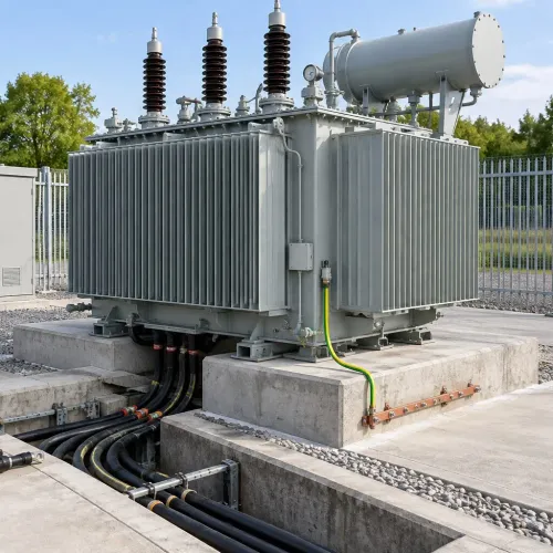
4. Obtain utility service characteristics and calculate available fault current through transformers, feeders, generators and other impedance. Check every board and protective device against the calculated interrupting rating; a transformer or service change can alter the result.
5. Separate emergency, legally required standby and optional standby loads. Confirm transfer equipment, circuit integrity, wiring separation, testing and accessibility for the adopted code and fire classification.
Treat telecommunications bonding under ANSI/TIA-607 and the adopted electrical code, not as an improvised connection to nearby steel. Record tray capacity, pathway routes, firestopping and future loading before choosing cables.
Select conductors and protective devices from calculated conditions
A 32 A breaker does not make a 32 A circuit safe. Select the conductor from the maximum demand, installation method, ambient temperature, grouping, insulation temperature rating and terminal limits, then select protection to match the cable and fault conditions.
Start with the connected load, apply the documented diversity factor, and calculate maximum demand for each feeder and final circuit. Add spare capacity for planned equipment without treating unused capacity as permission to exceed the cable’s corrected ampacity.
| Option | Selection point | Risk if mismatched |
|---|---|---|
| Copper conductor | Higher conductivity and compact terminations | Aluminium-sized assumptions cause overheating |
| Aluminium conductor | Suitable for larger feeders with approved lugs and joint compound | Poorly prepared terminations loosen or oxidise |
| XLPE insulation | Higher operating temperature and short-circuit withstand than PVC | PVC limits are applied incorrectly |
| Armoured cable | Mechanical protection and an earth path where designed | Unarmoured cable is damaged in exposed routes |
| Single-core cable | Large currents and easier parallel installation | Incorrect grouping or magnetic arrangement increases heating |
| Multicore cable | Compact fixed wiring and simpler routing | Excessive bending or heat reduces service life |
Check voltage drop as well as ampacity. The commonly cited 3% branch-circuit and 5% feeder-plus-branch-circuit figures are design guidance, but long feeders, motor starting, LED drivers and data equipment can still malfunction when voltage falls.
Obtain calculated available fault current at each panel. A breaker’s continuous rating is not its interrupting rating; verify the marked short-circuit rating, termination rating and any engineered series-rated combination. Include neutral harmonics in derating where nonlinear three-phase loads make the neutral carry current, and confirm the adopted local code edition with the AHJ.
Choose containment, segregation and fire protection for the installation
Route power and life-safety cabling in separate, supported pathways, then protect each rated penetration with a listed firestop assembly. A higher flame-spread rating does not replace pathway, support, separation or firestopping requirements.
| Containment | Best use | Controls to specify |
|---|---|---|
| Conduit | Individual feeders, risers, exposed routes and protected life-safety circuits | Raceway fill, bend radius, pull points, supports, bonding and fire-rated sleeves |
| Trunking | Grouped distribution circuits in accessible plant or service areas | Internal dividers, circuit identification, cover security, derating and separation from data cables |
| Cable tray | Large groups of permitted power or communications cables | Fill, cable weight, support spans, covers where required, bonding continuity and spare capacity |
| Ladder tray | Heavy feeders and cables needing ventilation and easy access | Load rating, side-rail support, cable restraint, clearances and future thermal capacity |
Keep variable-frequency-drive output cables, large feeders, transformers and motors away from sensitive copper communications routes; electromagnetic interference can disrupt service even when a minimum code separation is met. Separate pathways with barriers or distinct raceways when the adopted code, cable listing or system design requires it.
Plan dense Power over Ethernet bundles for conductor heating. Check bundle size, ambient temperature, pathway fill and the cable manufacturer’s limits, especially for IEEE 802.3bt installations. At walls, floors, shafts and smoke barriers, use a listed system matched to the penetrant, opening and assembly rating, with re-entry-capable sleeves for future cables.
Bond telecommunications pathways and racks through the telecommunications bonding infrastructure specified by ANSI/TIA-607 and the adopted electrical code.
Design structured cabling and extra-low-voltage pathways as complete systems
A complete design starts with an endpoint and pathway schedule, not a cable order. Show every data outlet, wireless access point, camera, access reader, controller, fire-alarm device, rack, patch panel, telecommunications room, riser and final termination; assign each a cable type, route, service loop and spare capacity.
Use this checklist:
- Define the topology: horizontal links from outlets and devices to patch panels, cross-connects between racks, and a fibre backbone between telecommunications rooms and building zones.
- Select media for the channel, not just the box label. Choose Cat6 or Cat6A after checking length, bandwidth, PoE load, connector compatibility and the required certification limit. Include patch cords, consolidation points and cross-connects in the channel calculation.
- Draw separate pathways for data, security, controls and fire alarm. Do not place them beside feeders, motor circuits, transformers or variable-frequency-drive output without checking the required separation, barriers, cable listings and electromagnetic interference risk.
- Specify supports, bend radii, pulling tension, fill limits, slack storage and access points. Overfilled trays and sharp bends can fail a nominal Cat6A or fibre installation.
- Identify plenum, riser, optical-fibre, Class 2/3 and fire-alarm cable listings for each space.
- Detail listed firestop systems at rated walls, floors, shafts and smoke barriers, including re-entry-capable sleeves for future cables.
- Set labels, rack elevations, device addresses, test criteria and as-built records before installation. Certify copper channels and fibre links, then record failed links and corrective work rather than accepting a visual inspection.
Verify, document and maintain the completed installation
Require a signed completion dossier before energisation: visual inspection records, test results, approved drawings, statutory approvals and maintenance information. Check workmanship against IS 732, the National Building Code of India 2016, the adopted utility rules and electrical inspector requirements; a passing energisation test does not excuse missing labels, exposed terminals or blocked panel clearances.
| Document | What it proves | Handover use |
|---|---|---|
| Insulation-resistance and continuity results | Conductors are intact and separated from earth | Establishes a baseline for future faults |
| Polarity, phase-sequence and protective-conductor tests | Devices will operate on the intended conductors | Prevents reversed supplies and motor damage |
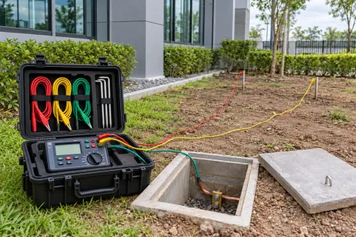
| Earth-electrode, earth-continuity and RCD trip records | Fault current has a safe path and protection trips | Supports periodic safety testing |
| Functional and emergency-system tests | Lighting, alarms, interlocks, transfer equipment and controls operate together | Confirms life-safety performance |
| Electrical inspector approval and test-instrument calibration certificates | The inspection authority accepted the installation and measurements are credible | Closes statutory and audit gaps |
For a project handled by Navyashree Engineers Private Limited, request the same dossier in editable and signed formats, not only a commissioning certificate.
Include these handover controls:
- As-built drawings showing cable routes, circuit numbers, panel schedules, containment, earthing and fire-stopping locations.
- Cable schedules, protection settings, equipment manuals, warranty details and spare-parts lists.
- A maintenance plan stating inspection intervals, isolation points, lockout/tagout steps and who may work on energised equipment.
Label every panel, isolator and cable end before occupancy. Record later alterations against the as-built drawings.
Related products
 | Commercial Electrical Contractors Commercial Electrical Contractors Navyashree Engineers, is a professionally managed class 1 Electrical contractors in South india. View product → |
 | Electrical Design Consultants Navyashree Engineers provides high quality electrical system design & engineering capability, electrical project consultancy and construction... View product → |
Frequently asked questions
How do you map electrical layers in a commercial building?
Start at the service entrance, then map the main distribution board, sub-distribution boards and final circuits. List lighting, sockets, equipment feeders, HVAC and low-voltage systems separately.
What must you calculate before selecting commercial cables?
Calculate maximum demand, design current, voltage drop, prospective fault current, installation method, ambient temperature and grouping. Use these conditions to select conductor sizes and protective devices.
How should power and low-voltage cabling be separated?
Use dedicated containment or specified partitions for power, data, fire alarm, access control and security cables. Maintain separation, label routes and protect pathways from heat, water and mechanical damage.
What records should you keep after completing the installation?
Keep test results, circuit schedules, cable routes, panel directories, as-built drawings, equipment manuals, inspection records and maintenance dates.
Related product
 | Licensed Class 1 Electrical Contractor Licensed Class 1 Electrical Contractor Navyashree Engineers is a leading class 1 licensed electrical contractors in Bangalore. View product → |